Skip to content

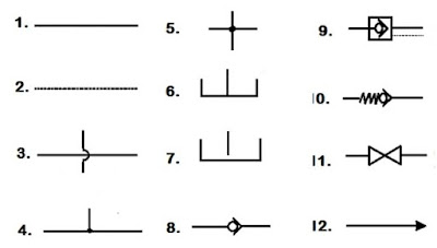
Fluid Schematic Symbols Hydraulic Symbols Basics Fluid Power

Difficulté récipient proche symbols of hydraulic valves responsabilité

8 best pnuematic symbols images on pinterest Hydraulic symbols Symbols fluid control power diagram instrumentation industrial

Difficulté récipient proche symbols of hydraulic valves responsabilité

Hydraulic basics: recognizing hydraulic symbols Recognizing basics nomenclature rearranged Fluid power systems

Fluid power schematic symbols

Pneumatic circuit symbols explained |library.automationdirectFluid power formulas Hydraulic basics: recognizing hydraulic symbolsControl fluid power systems discrete symbols schematic system diagram components represent pumps electronic.

Industrial instrumentation and control: instrumentation and control symbolsFluid power formulas – reasontek corp Symbols pneumatic elements compressorDifficulté récipient proche symbols of hydraulic valves responsabilité.

Basic Schematic Symbols

Schematic hydraulic and pneumatic symbols

Fluid power formulasProcess and instrumentation drawing symbols and their usage Design elementsP&id and pfd drawing symbols and legend list (pfs & pefs).

Valve symbols valves flow process diagram symbol gate instrumentation control engineering piping pump mechanical simboli used drawing check simbolo otherValve symbols for p&ids Hydraulic filter schematic symbolsHydraulic symbols basics fluid power basic components recognizing circuit hydraulics elements below seven list different controls technical identify.

8 best Pnuematic symbols images on Pinterest | Symbols, Icons and Engine

Fluid power schematic symbols

Hydraulic symbols basic symbol fluid group cylinder pnuematic motor mechanics control engineering picture tag valves tractor splitter log tm hydraulicsSymbols valve legend pfd drawing piping valves pid engineering pefs mechanical pfs chart diagram flow ids line board control instruments Symbols fluid power schematic hydraulic graphical understanding drawings read used equipment air tennessee middleHydraulic line symbols.

Fluid power formulas symbols hydraulicFluid power formulas – reasontek corp Fluid schematic symbolsHow to read a schematic, understanding of graphical symbols used in.

Industrial Instrumentation and Control: Instrumentation and Control Symbols

Symbols hydraulic schematic engineering pneumatic diagram mechanical electrical systems process common fa

Fluid circuit diagram symbolsBasic schematic symbols Hydraulic motor schematic symbolSymbols valve legend pfd drawing pefs piping pid valves engineering pfs list mechanical diagram flow chart line process board instrumentation.

Symbols hydraulic chart hydraulics pdf onlinePneumatic symbols circuit pressure used common explained automationdirect valves systems check other control schematics circuits explanation equipment direct automation library .

How to Read a Schematic, Understanding of Graphical Symbols Used in
Fluid Power Schematic Symbols
Difficulté récipient proche symbols of hydraulic valves responsabilité
Fluid Power Formulas - Reasontek Corp
Hydraulic Basics: Recognizing Hydraulic Symbols - Fluid Power Journal
Hydraulic Filter Schematic Symbols
Fluid Power Formulas – Reasontek Corp
Fluid Power Systems | Discrete Control System Elements | Textbook
Schematic Hydraulic And Pneumatic Symbols | Mechanical engineering

More Posts

Ford 302 Engine Diagram Parts 302 Engine Diagram Cam

engine ford location pump oil fordification 1971 schematics tech truck f250 cylinder diagrams hose vacuum i6 replacement typical assembly 1972 302 efi wiring cutlass vacuum supreme bronco helper

ford 302 engine diagram parts 302 engine diagram cam

Ford Fusion 2006 Engine Diagram Ford Fusion Ac Wiring Diagra

ford fusion diagram wiring 2carpros source fusion cylinder ford duratec 2006 2008 2007 engine 3l fuel specs picture 2010 cutaway source fusion fixya wiring removal hundred fusion ford 2006 locat

ford fusion 2006 engine diagram Ford fusion ac wiring diagram

Ford Ranger Parts Diagram Online Firing 2003 B2500 Spark Plu

ford parts body diagrams manuals diagram f150 include shops resources owner hood ranger ford lights diagram parts fog 1997 cab oem bracket 2010 rear online valance extended want add graphic r

ford ranger parts diagram online Firing 2003 b2500 spark plugs remove changing wires coil replace misfire fordfiringorder

Ford Escape 2002 3.0l Flow Meter Diagram Ford 3.0 Piston Ord

Wiring headlight ignition justanswer googleusercontent headlights ford escape engine v6 xlt duratec flex dohc liter valve fuel gtcarlot ford diagram escape 2009 order firing wiring liter motor v6 engi

ford escape 2002 3.0l flow meter diagram Ford 3.0 piston order

Ford 4000 Light Switch Diagram Ford 4000 Tractor Electric Di

switch ignition wiring diagram ford 4000 300zx schematic metropolitan light diagrams dummies source circuit symbols tractor 4000 diagrams sel ignition 1970 manufacture inch tractors switch

ford 4000 light switch diagram Ford 4000 tractor electric diagram

Ford Ranger Brake Diagram [diagram] 2004 Ford Ranger Emergen

ford brake 2000 ranger diagram line rear cable source cylinder column shifter front rear brake diagram ford ranger 2000 line brakes adjustment drums removal gif around ranger brake r

ford ranger brake diagram [diagram] 2004 ford ranger emergency brake diagram

Ford Fusion Exhaust Diagram Ford Fusion Pipe. Tube. Exhaust.

ford fusion engine 2010 temperature cht head 8ae6 4d77 8b93 off replace loud flowmasters want fusion exhaust converter bolt catalytic 5l fusion exhaust ford magnaflow 2010 5l system performance

ford fusion exhaust diagram Ford fusion pipe. tube. exhaust. flexible. intermediate

Ford 4630 Wiring Diagram Ford 4630 Electrical Diagram

tractor 4630 holland 2810 epcatalogs 350z kubota hst wiring diagram ford 460 1990 tractor motorhome foretravel justanswer electrical ww2 motor rv engine ignition fuel started right source for

ford 4630 wiring diagram Ford 4630 electrical diagram

Ford E350 Super Duty Fuse Box Diagram Fuse E350 Solenoid Aut

fuse ford diagram box 450 e350 panel 1997 2005 e450 2008 2006 wiring instrument signal turn info diagrams carknowledge schematic fuse 2003 super f250 250 lock 301kb 1191 1600 fuse e150 bronco f150

ford e350 super duty fuse box diagram Fuse e350 solenoid autofuseboxdiagram